
Frequently Asked Questions
Our FAQ page is designed to provide quick, clear answers to common questions about AJA International’s thin-film deposition systems, services, and capabilities. Whether you are exploring system configurations, technical specifications, applications, or support resources, this section serves as a helpful starting point to guide your evaluation and streamline your experience with AJA. If you need additional assistance, our team is always available to provide personalized support.
-
The phenomenon of "Bent Plasma" is a common illusion in confocal sputtering systems. It's an "illusion" not because it isn't there, but that it gives the illusion that sputtered material is going somewhere other than the substrate. Plasma streams are the result of electrons from the plasma, moving in the direction of diminishing magnetic fields and away from the plasma itself to compensate for the loss of ions toward the cathode. These plasma streams show the path of charged species only, not the primarily neutral sputtered material which travel primarily in a straight path.
-
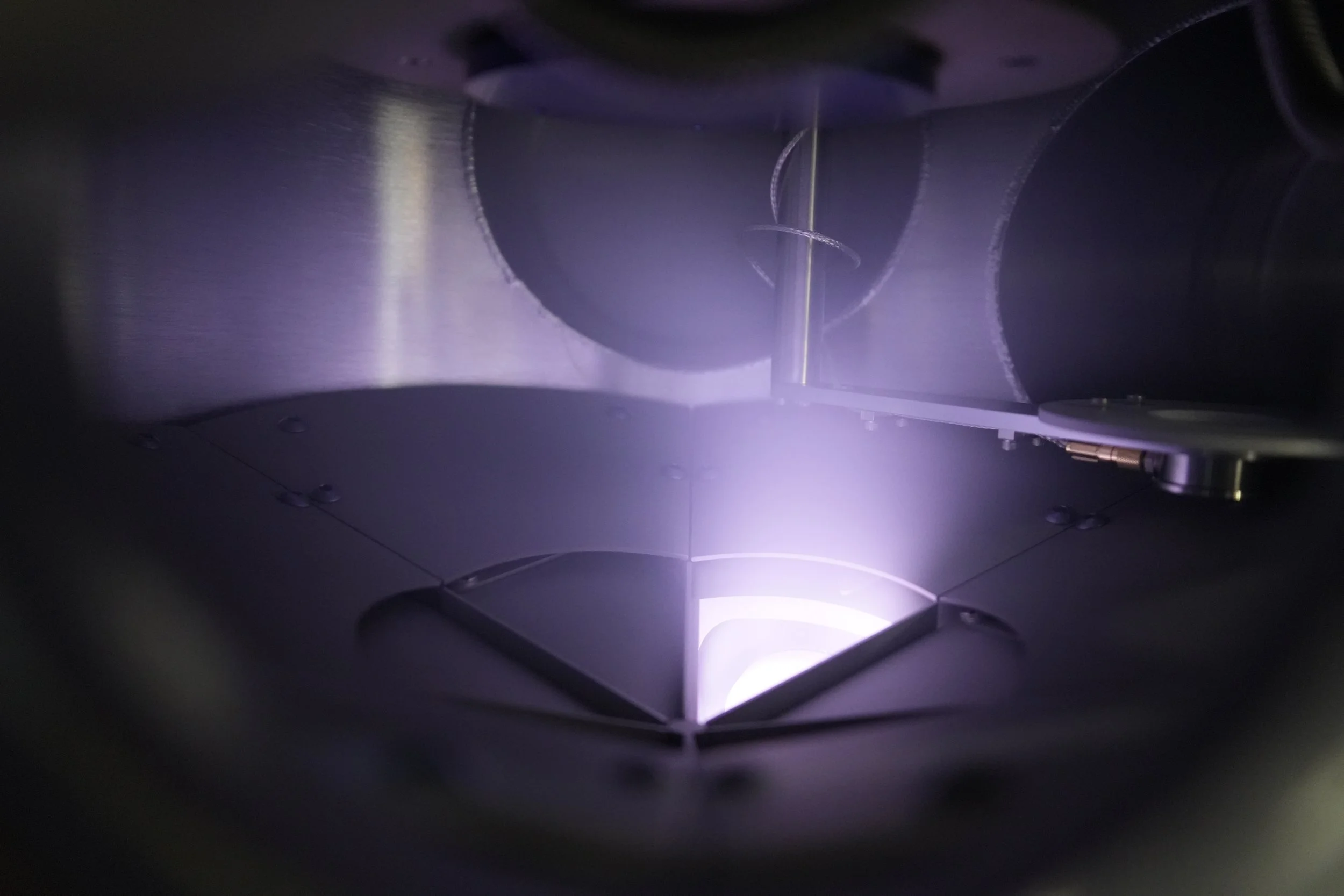
The color of the plasma in magnetron sputtering – besides being beautiful – is indicative of the gas content, the sputtered material and the ionization fraction. These properties shift with different gas and target combinations but are primarily gas driven due to the energy released in the form of photons. Most of the time when color changes during a run, a different gas has been introduced. The discharge gas, typically Argon (Ar), creates a characteristic purple/lavender glow. Introducing other gases like Oxygen (O2) produces a white-blue glow, while Nitrogen (N2) produces a pink-purple color. So if the plasma has shifted colors, most likely the conditions are not of a pure Ar environment and the gas should be checked along for any minor leaks in the chamber.
-
Each AJA tool is specifically designed to have a water interlock loop and a vacuum interlock loop. The water interlock loop can be generalized as a tool safety interlock, where the vacuum interlock can be generalized as a user safety interlock.
Water interlock: This is primarily in place to keep the system safe during operation. The cooling loops typically feed 3 major components: Sources, Pumps and Heating/Cooling stages. Without cooling water in place, operation of these units could end in catastrophic failure. Each cooling loop (on average between 3 and 6 zones) has its own flow sensor which is wired in series through a set of relays. Even if 1 of these loops has an issue, it will shut down the tool and activate the water interlock LED so you know to check for a flow problem.
Vacuum Interlock: The vacuum interlock is in place at 660 Torr. If the system is under vacuum, below 660 Torr, power will be supplied to the power supplies, heater controller, or any other device requiring a safety interlock. If the pressure is above 660 Torr, power is shut down to these interlocked devices, not allowing you to turn them on or operate in an unsafe condition. For example, while changing target materials in a source, one cannot accidentally turn on a DC power supply to 200W while your hand is on a live cathode.